Program a microcontroller
Write simple code to program a microcontroller board (like Arduino) to blink LEDs, read a sensor, and control a buzzer for basic projects.


Step-by-step guide to program a microcontroller board
PROGRAMMING for kids 👦 Basic concepts 💻 Part 1
Step 1
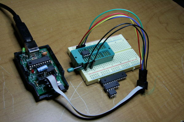
Gather all the materials on a clear table so you can see everything and work safely.
Step 2
Plug the USB cable from the microcontroller board into the computer to power and program the board.
Step 3
Insert an LED into the breadboard and connect its long leg to digital pin 9 and its short leg to ground through the 220Ω resistor.
Step 4
Put the photoresistor on the breadboard and wire it as a voltage divider: one side to 5V the other side to analog pin A0 and add the 10kΩ resistor from that A0 row to ground.
Step 5
Connect the piezo buzzer positive lead to digital pin 8 and the buzzer negative lead to ground.
Step 6
Open the Arduino IDE on the computer and create a new sketch so you can type or paste your program.
Step 7
Copy and paste this code into the new sketch exactly as shown:
Step 8
In the Arduino IDE choose the correct board model and the correct serial port so the computer can talk to your microcontroller.
Step 9
Click Upload in the Arduino IDE to send the program to your board and wait for the "Done uploading" message.
Step 10
Open the Serial Monitor in the IDE to watch live sensor numbers so you can see how bright or dark the sensor reads.
Step 11
Test the project by covering the photoresistor with your hand to make it darker and listen for the buzzer while watching the LED blink.
Step 12
If the buzzer is too quiet or not triggering, change the threshold number in the code to a higher or lower value and upload again to tune when the buzzer sounds.
Step 13
Take a photo or video and share your finished blinking LED sensor project on DIY.org so others can see your awesome work.
Help!?
What can I substitute for hard-to-find parts like the 220Ω resistor, 10kΩ resistor, photoresistor, or piezo buzzer?
If you can't find a 220Ω resistor for the LED on digital pin 9, use 330Ω; if you lack the 10kΩ in the photoresistor voltage divider to A0 try any 4.7–47kΩ and re-tune the code threshold, use a 10k potentiometer wired between 5V and ground with the wiper to A0 instead of a photoresistor, and replace the piezo on digital pin 8 with a small active buzzer or amplified speaker (checking polarity).
My upload failed or the LED/buzzer doesn't work—what should I check first?
Check the USB cable and that you selected the correct board model and serial port in the Arduino IDE, verify the LED long leg is in the row tied to digital pin 9 and the 220Ω resistor goes to ground, ensure the photoresistor and 10kΩ resistor form the voltage divider at A0, and if the buzzer on pin 8 is quiet try raising or lowering the threshold number in the code and re-upload.
How can I adapt this activity for different ages or skill levels?
For ages 5–8 have an adult pre-upload the sketch and let the child place the LED and press 'Open Serial Monitor', for ages 9–12 supervise them while they wire the LED to pin 9, photoresistor divider to A0, and buzzer to pin 8, and for teens have them modify the code, add calibration, and log Serial Monitor values themselves.
How can we extend or personalize the blinking LED sensor project after it works?
Add an RGB LED on multiple digital pins to change color with light level, program multiple buzzer tones for different thresholds, write a calibration routine in the sketch to set the threshold from live Serial Monitor readings, or mount the circuit in a decorated box and record a video to share on DIY.org.
Watch videos on how to program a microcontroller board
Pico Course for Beginners | Coding, Electronics and Microcontrollers
4 Videos

Pico Course for Beginners | Coding, Electronics and Microcontrollers

Want To Learn A Microcontroller? Start Here. | Raspberry Pi Pico Workshop: Intro
PROGRAMMING for kids 👦 Block Programming 💻 Part 2

Kindergarten Kids Learning Videos Compilation
Facts about microcontrollers and beginner electronics
🔌 Microcontrollers are tiny computers on a chip — many hobby boards have only a few kilobytes to a few dozen kilobytes of memory!
🇮🇹 Arduino began in Italy in 2005 to help artists and students build easy, affordable electronics projects.
💡 LEDs turn on instantly, use far less energy than incandescent bulbs, and can last tens of thousands of hours.
🔔 Piezo buzzers make sound by flexing a crystal with voltage — they can beep without a full speaker cone.
🕵️♀️ Simple sensors like photoresistors change electrical resistance with light, letting microcontrollers 'sense' brightness.
How do I teach my child to program a microcontroller to blink LEDs, read a sensor, and control a buzzer?
What materials do I need to program a microcontroller board for simple LED, sensor, and buzzer projects?
What ages is programming a microcontroller suitable for?
What are the benefits and safety tips for kids programming microcontrollers?
